Page 2 of 4
Re: rudog#1
Posted: Wed Feb 29, 2012 12:31 pm
by rudog
Thanx, guys. I have a skill set with machinery, but all I know about tube I learned from yous guys.
Re: rudog#1
Posted: Thu Mar 01, 2012 1:56 pm
by joey3380
real cool frame design
Re: rudog#1
Posted: Thu Mar 01, 2012 7:30 pm
by rudog
Thanx. I gotta finish it quick. I can't stop walking over and measuring something.
Next step is the post and backbone. I've moved the tank as far forward as I dare. That gives me about 40* rotation for the forks without hitting the tank with the upper yoke. I don't need it but it's nice to have.
I'm setting the rear axle location now. I'm having to sneek up on where the wishbones meet the backbone. I've got a particular leafspring mount in mind and it's not looking like it's gonna happen.
Re: rudog#1
Posted: Thu Mar 01, 2012 10:19 pm
by hansgoudzwaard

Are you using these measurements as a guideline?
Re: rudog#1
Posted: Fri Mar 02, 2012 12:23 am
by rudog
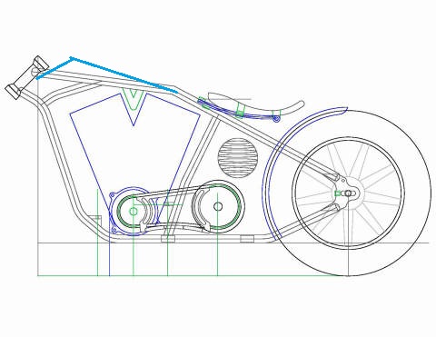
For the most part I am, Hans. I've made alot of choices from the CR140-2 plans. They are all pretty much similar. I've bent the seat post like in my drawing. I plan to reverse bend it to pull the junction back closer to the head.
The bend in the backbone will be a little farther back than in my drawing, but still do-able. The problem with the leafer mount is that I've got it in my head to put the leaves between the wishbones and not on top. I'm thinking to do that I may need to bend the backbone twice.
The picture in my head is fuzzy, I can see a reciever welded on top of the wishbone intersection, and a perch welded above the seat post. When I design machines, I try not to use bolts for working strength...only to keep it together when you shake it.
With the reciever and perch my own body weight will hold it in place. The bolts are only for when I'm not in the seat. I'll have to take it slowly...one step at a time. If I can sharpen the picture in my head and make it a reality, it should be pretty trick and functional.
I'll post another pic when I get the wishbones sorted out. I still need to set my final wheelbase.
Re: rudog#1
Posted: Fri Mar 02, 2012 2:01 pm
by yona
rudog wrote:That wasn't so bad. Tedious and time consuming, but it came out better than I thought.
fab19.JPG
fab16.JPG
That is what i meant ....the oblique edges have more weld area than just round circles... ; )
Re: rudog#1
Posted: Fri Mar 02, 2012 2:53 pm
by yona
rudog wrote:Thanx Hans. The tube from the backbone to the curve of the gooseneck will be added. With the angle that the tube will be welded to the neck, it should be plenty strong.
This is what it's planned to look like.
The attachment frametmp Model (1.jpg is no longer available
Tried to make a drawing in paint ...lol..... But since we have talked about this seat and I have worked on my version , these were my thoughts !
Bend the bar up close to the top mount or curve till it will over lap the seat mount area and cut a pocket in the end or shape to a
rectangle to fit the spring in and drop a bolt thru it ...add a x-bar for the spring to sit on and try to curve the seat post till it come up under the top bar to clear the mount area....this is how I thought of doing mine !
Re: rudog#1
Posted: Fri Mar 02, 2012 3:30 pm
by rudog
Thanx, YONA. That hits the nail on the head. I was trying to work it out with straight ends. The loop may solve the problem if my bender will do it (and the bender with his hand on the pump). I may have enough excess in the backbone to make the curve. Then splice to the seat post.
To get my 70* die to do the 90*plus will be a challenge.
The backbone being bent farther forward will require modifying the tank tunnel. I wanted to modify the tank as little as poss.
Re: rudog#1
Posted: Fri Mar 02, 2012 10:05 pm
by rudog
Here's some eye candy for those interested. Your seein' this only minutes after I did so I've not had time to digest it. The seat will naturally be farther back and down. Wishbones are @30* the lower rail @25*. Ive set the axle for 5" ground clearance. The wishbones will meet at the tank rear mount.

- fab20.JPG (27.83 KiB) Viewed 6262 times
I will replace the front tank mount with hidden mounts. I was thinking of bending the lower lip of the tank into the tunnel. That's still a "might not until I do". I was thinking of closing the tunnel to fit the tube, but you can't see the tunnel, and I can hide shit in there.
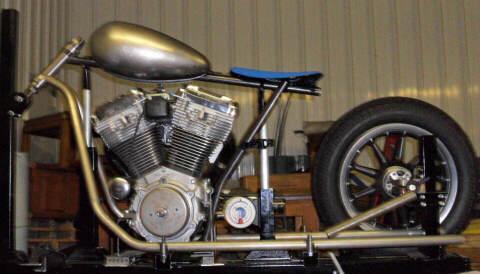
- fab21.JPG (26.25 KiB) Viewed 6262 times
Re: rudog#1
Posted: Fri Mar 02, 2012 10:08 pm
by hansgoudzwaard
Trying to portray an idea here. Why not move the backbone bend further up toward the neck, trying to keep the backbone straight as regards the tank tunnel.
- frametmp%20Model%20(1.jpg (40.5 KiB) Viewed 6262 times

- IGOTALLKINDSOFDISCHIT!
- cheapc30BAREFOOT_J.jpg (56.63 KiB) Viewed 6260 times
Re: rudog#1
Posted: Fri Mar 02, 2012 10:25 pm
by rudog
I beat you by 3min, Hans.
The thought was long and low. The tank kinda threw me off track when I measured how long it was. It's 3 1/2 gal. The 1st draft had the backbone horizontal, and the tubes @65* rather than 78*...that's digger country.
What your showing there is basically a 1948 with a dropped neck. What YONA described is what I need to try and do. The only compromise is if the leaf spring sits on top of the frame or inside it.
I wish I wouldn't have mocked that up tonight. Now I'll never get to sleep.
Re: rudog#1
Posted: Sat Mar 03, 2012 2:16 am
by railroad bob
In the photo posted by Hans, I notice that the backbone and frame tube below it parallel the rocker covers of the engine, almost like a picture frame.
Hence the phrase, pretty as a picture...
Sorry, couldn't help myself.
Re: rudog#1
Posted: Sat Mar 03, 2012 7:53 am
by yona
if you mod that 70 degree die to look like this , the over 90 bend is a piece of cake .....the smaller die are easier to remove from the bend ! of course you always can go to far... ; ) You need to put a little spug on the tube so the die will not bind..... but i know a machinist that can make you a smaller radius die , but there is no need, as that mod works........; ))))
Re: rudog#1
Posted: Sat Mar 03, 2012 9:44 am
by Maxthegardener
Hans shows a nice pic of Barefoot Gerrys frame, was trying to find the build log thats on his site....cant find it for some reason...I do remember though, on the overhang of the back bone past the seat post was cut horizontally to make a flat which would make an ideal mounting for the seat
Re: rudog#1
Posted: Sat Mar 03, 2012 11:27 am
by rudog
I'm gonna live with this for a few days. I got freebee's and payme's to do and this is a perfect time to stop. I figured out how to drop the leaf between the wishbones without much problem from the seat post.
What if I rotated the wishbones around the backbone to create a v-groove for the spring perch. I've never seen it done that way. It would look from the side like the drawing Hans did for the backbone. I would only need 1/2" +/-.