Updated springer build rules
Posted: Mon Jan 21, 2013 2:33 pm
Springer Rules of Thumb:
I have written down what I believe to be the rule for setting up a springer rocker mounting system. We have been working on and refining the rule and I will put out the initial writing while redefining the rules. I recognize the needed trail number to be 3.375” of ground trail with the bike in the unweighted position. I also adhere to a rear tire width that is 200% larger than the front tire width to set my trail at 3.375. Attached is a rule I use to account for the difference of rear tire width if smaller or larger than the 200%.
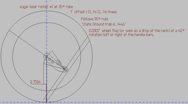
The 90* angle rule: this rule was set up to dictate the proper measuring and assembly of the springer rockers. First and foremost do not have any weight on the frontend. I block the front of bike frame with 2x4 and shimming stock. I set the front of the frame.75 to 1" above the final position of the weighted frame (containing motor transmission and rider). For lighter riders (200# or less) I set closer to .75", for riders 200# or more I go a full 1". This rule dictates the position of the rear (rigid leg) rocker attachment hole. That in turn will tell you where to place your spring leg attachment hole.
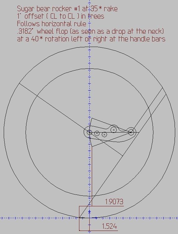
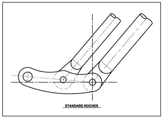
The horizontal zero rule: set a horizontal zero line that intersects centerline of axle, centerline of spring leg, and centerline of rigid leg. Proceed the same way you would set the 90* rule with bike setup.
The tire width rule: trail should be set to 3.375” of ground trail when the rear tire is 200% larger than the front tire (i.e.: front tire is 90/90/21 and rear tire is 180/55/18 the rear tire width is 200% larger). If the rear tire is not 200% larger the following equation will help adjust the trail.
Trail Adjustment= [{(rear tire width/front tire width)x100}-200]0.01
-if the number is positive add the answer to the 3.375” of initial trail
-if the number is negative subtract the answer from the 3.375” of initial trail
Eample: 90/90/21 front tire, 250/40/18 rear tire
[{(250/90)100}-200]0.01=
[{(2.78)100}-200]0.01=
[{277.78}-200]0.01=
[77.78]0.01=.78~
.78+original trail of 3.375= 4.155” of total adjusted ground trail
- About .78” (disregarding of infinites and using only three decimal places) of trail adjustment would be needed to account for the use for the example tires. Had the answer been a negative number, you would have subtracted from the original ground trail of 3.375.
Eample: 90/90/21 front tire, 140/90/16 rear tire
[{(140/90)100}-200]0.01=
[{(1.556)100}-200]0.01=
[{155.56}-200]0.01=
[44.44]0.01=-.44~
-.44+original trail of 3.375= 2.935” of total adjusted ground trail
Rule 1: place the blade (the long end) of a carpenter's square along the centerline of the steering axis. If not using raked trees, raked cups, or offset trees you can simplify this and use the centerline of the rigid leg of the springer. Align the tongue (the shorter leg) of the carpenter's square with the centerline of the axle. If using the centerline of the rigid leg, the point of the square will be where you should place your rigid leg rocker attachment hole. With this hole made you can in turn make the spring leg rocker attachment hole by setting a level at horizontal zero along the centerline of the rigid leg rocker attachment hole. Follow the horizontal zero forward to the intersection of the centerline of the spring leg. The point of intersection is where the spring leg rocker attachment hole should be placed. Once the frame is taken off the cribbing and the weight is applied to the frame, the rockers will preload the spring leg and naturally set the rocker attachment holes 10-20* of horizontal zero.
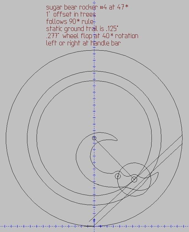
Rule 2: expanding upon rule one, if the 90* rule cannot be utilized in a flowing rocker design you may have to go to the horizontal zero rule, and that is: if a 90* cannot be achieved then set a horizontal zero line that intersects centerline of axle, centerline of spring leg, and centerline of rigid leg. This will place the unweighted rocker attachment hole in horizontal alignment with the axle. There by getting the rocker holes to be at a 10-20* off of horizontal zero along the centerline of the rigid leg attachment hole.
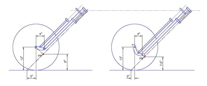
A good diagram from Gary Weishaupt shows the 90* angle rule and how it will affect trail and design. An example of using the horizontal zero rule would be Gary’s rude crude radiused rocker. By setting the rocker holes to zero unweighted, when the weight is applied then the springs automatically preload and set the proper angular relationship. Gary’s diagram and the point marked PR is what we are trying to achieve, realize this chart is of the frontend in the weighted position
here is garys radiused rocker in the weighted position
Some things to take into account is
1. I am using ground trail
2. I am using trail in the unweighted position
Building in the unweighted means that the cyclical action will never go below the listed ground trail. I feel good about building this way. You don’t have to be afraid to disagree or add on also. Also you will see the 90* rule is based on steering axis centerline. This coincides with true trail measuring. I believe this is why it sense.
I have written down what I believe to be the rule for setting up a springer rocker mounting system. We have been working on and refining the rule and I will put out the initial writing while redefining the rules. I recognize the needed trail number to be 3.375” of ground trail with the bike in the unweighted position. I also adhere to a rear tire width that is 200% larger than the front tire width to set my trail at 3.375. Attached is a rule I use to account for the difference of rear tire width if smaller or larger than the 200%.
The 90* angle rule: this rule was set up to dictate the proper measuring and assembly of the springer rockers. First and foremost do not have any weight on the frontend. I block the front of bike frame with 2x4 and shimming stock. I set the front of the frame.75 to 1" above the final position of the weighted frame (containing motor transmission and rider). For lighter riders (200# or less) I set closer to .75", for riders 200# or more I go a full 1". This rule dictates the position of the rear (rigid leg) rocker attachment hole. That in turn will tell you where to place your spring leg attachment hole.
The horizontal zero rule: set a horizontal zero line that intersects centerline of axle, centerline of spring leg, and centerline of rigid leg. Proceed the same way you would set the 90* rule with bike setup.
The tire width rule: trail should be set to 3.375” of ground trail when the rear tire is 200% larger than the front tire (i.e.: front tire is 90/90/21 and rear tire is 180/55/18 the rear tire width is 200% larger). If the rear tire is not 200% larger the following equation will help adjust the trail.
Trail Adjustment= [{(rear tire width/front tire width)x100}-200]0.01
-if the number is positive add the answer to the 3.375” of initial trail
-if the number is negative subtract the answer from the 3.375” of initial trail
Eample: 90/90/21 front tire, 250/40/18 rear tire
[{(250/90)100}-200]0.01=
[{(2.78)100}-200]0.01=
[{277.78}-200]0.01=
[77.78]0.01=.78~
.78+original trail of 3.375= 4.155” of total adjusted ground trail
- About .78” (disregarding of infinites and using only three decimal places) of trail adjustment would be needed to account for the use for the example tires. Had the answer been a negative number, you would have subtracted from the original ground trail of 3.375.
Eample: 90/90/21 front tire, 140/90/16 rear tire
[{(140/90)100}-200]0.01=
[{(1.556)100}-200]0.01=
[{155.56}-200]0.01=
[44.44]0.01=-.44~
-.44+original trail of 3.375= 2.935” of total adjusted ground trail
Rule 1: place the blade (the long end) of a carpenter's square along the centerline of the steering axis. If not using raked trees, raked cups, or offset trees you can simplify this and use the centerline of the rigid leg of the springer. Align the tongue (the shorter leg) of the carpenter's square with the centerline of the axle. If using the centerline of the rigid leg, the point of the square will be where you should place your rigid leg rocker attachment hole. With this hole made you can in turn make the spring leg rocker attachment hole by setting a level at horizontal zero along the centerline of the rigid leg rocker attachment hole. Follow the horizontal zero forward to the intersection of the centerline of the spring leg. The point of intersection is where the spring leg rocker attachment hole should be placed. Once the frame is taken off the cribbing and the weight is applied to the frame, the rockers will preload the spring leg and naturally set the rocker attachment holes 10-20* of horizontal zero.
Rule 2: expanding upon rule one, if the 90* rule cannot be utilized in a flowing rocker design you may have to go to the horizontal zero rule, and that is: if a 90* cannot be achieved then set a horizontal zero line that intersects centerline of axle, centerline of spring leg, and centerline of rigid leg. This will place the unweighted rocker attachment hole in horizontal alignment with the axle. There by getting the rocker holes to be at a 10-20* off of horizontal zero along the centerline of the rigid leg attachment hole.
A good diagram from Gary Weishaupt shows the 90* angle rule and how it will affect trail and design. An example of using the horizontal zero rule would be Gary’s rude crude radiused rocker. By setting the rocker holes to zero unweighted, when the weight is applied then the springs automatically preload and set the proper angular relationship. Gary’s diagram and the point marked PR is what we are trying to achieve, realize this chart is of the frontend in the weighted position
here is garys radiused rocker in the weighted position
Some things to take into account is
1. I am using ground trail
2. I am using trail in the unweighted position
Building in the unweighted means that the cyclical action will never go below the listed ground trail. I feel good about building this way. You don’t have to be afraid to disagree or add on also. Also you will see the 90* rule is based on steering axis centerline. This coincides with true trail measuring. I believe this is why it sense.